All there is to know about fan drive controls
March 3, 2021
Fan drives are central to a truck’s engine cooling system, controlling fan speeds to provide ample cooling without using too much energy. But how does a fan drive, or clutch, “know” how fast the fan needs to turn?
The answer: controls.
Fan drive controls vary by fan drive type and vehicle, but their essential purposes is to send important information or signals from the engine to the drive so it provides optimal RPMs.
Say the word “controls” in a shop or engineering staff meeting, and you might get a sideways look. When set up and programmed correctly, they’re a huge benefit. Use the wrong one or miss a step in configuring them, it can be a headache.
Here’s everything to know about fan drive controls.
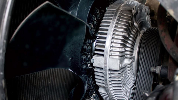
The heart of the control system
The solenoid valve can be thought of as the “heart” of the control system, opening and closing to regulate airflow to the fan drive.
The solenoid valve is a three-way valve with two inlet/exhaust ports and one outlet port. Air pressure from the vehicle’s air system is fed into one of the inlet ports, and the outlet port is connected to the fan drive.
Turning the electric current on and off causes a plunger inside the solenoid valve to move up and down. The plunger connects the valve outlet port to one of the two inlet ports:
- The normally open port when the electric current is off
- The normally closed port when the electric current is on
The valve has a 3/64-inch (1.19 mm) orifice to regulate the volume of air and ensure smooth engagement and disengagement of the fan drive.

The valve outlet port is always connected to the fan drive. Depending on the vehicle’s electrical control circuits, the air supply may be connected to either the normally open or the normally closed port.
The port not connected to the air supply will exhaust air from the fan drive when it disengages. Various adapters and fittings are available to permit the solenoid valve to be plumbed either normally open or normally closed (the air supply may be connected to either inlet port). These fittings also permit the solenoid valve to be installed with or without an air filter.
The solenoid valve should be mounted in a remote location away from the engine to minimize the valve’s exposure to excessive heat, vibration and contaminants. A solenoid valve mounted off the engine will prolong the life of the solenoid and ensure proper fan drive operation.

Wired for airflow
The electrical wiring that controls the fan drive varies from one vehicle to another but generally will be one of three types of systems:
- ECM Controlled: Solenoid valve is "normally Closed" and controlled by sensors
- Normally open: Current is required to close the solenoid valve
- Normally Closed: Current is required to open the solenoid valve
Engine manufacturers include electronic control modules (ECMs) in their new designs to control the engine, transmission and other critical operations to improve engine performance, reliability and fuel efficiency.
An ECM is essentially a digital computer, containing a microprocessor, random-access memory (RAM) and read-only memory (ROM). The ROM contains the computer’s program.

Design engineers can change a vehicle’s control system and engine performance simply by changing the ECM’s programming.
Electronic control modules are simpler and more reliable than independent hard-wired systems. The decision logic is in the computer program and not the wiring, and all sensors and actuators are wired to the ECM instead of to each other. Most ECM-controlled engines are equipped with a "normally closed" solenoid valve.
Making sense of engine signals
The ECM computer monitors the data from engine-mounted sensors and sends the appropriate signals to the controls and actuators based on programming logic. The ECM also sends status information to the operator’s warning lights and gauges.
In an ECM-controlled system, one sensor may affect several actuators, and one actuator may be affected by several sensors, depending on how the ECM is programmed.
Sensors used in ECM systems are different than those used in independent systems. Instead of the simple open/close type of sensor, ECM systems use thermistors and sending units to send signals to the ECM (temperature, pressure, speed or whatever function is being sensed).
[RELATED: Find a full listing of engine cooling parts and cross-reference data inside Horton's online catalog.]
The fan drive solenoid is not wired to the sensors as it is in a conventional system but instead to a relay controlled by the ECM. The ECM computer program looks at the data from several sensors and decides when to engage and disengage the fan drive. The program considers engine coolant temperature, air conditioner’s refrigerant pressure, intake-manifold air temperature, engine speed and engine brake status and possibly other factors, depending on engine configuration.
New troubleshooting techniques may be necessary when working on a truck with an ECM control system. A vehicle’s wiring diagram no longer indicates which sensor affects which actuator. The diagram only shows which ECM pin each sensor and actuator is connected to.
To determine relationships between sensors and actuators, you can refer to the vehicle or engine service manual for descriptions of exact conditions -- usually in the form of fault codes -- under which each actuator is engaged.
Cool under pressure
The diagram above also shows the pressure protection valve. The pressure protection valve is a “fail-safe” device used to prevent damage and excess fan drive friction wear when the system air pressure goes below 90 psi.
When that happens, the pressure protection valve will open the circuit, interrupting current flow to the solenoid valve and deactivating it. This stops airflow to the fan drive, resulting in fan drive engagement.
Once the system air pressure reaches 90 psi, the pressure protection valve will close, completing the circuit, activating the solenoid valve. Activation of the solenoid valve will allow air to flow to the fan drive, disengaging the fan drive.
^Watch: How to perform preventive maintenance on a semi-truck engine cooling system
Testing the pressure protection valve:
A simple test of the pressure protection valve can by conducted with the vehicle running. When the fan drive is disengaged (no engine cooling required, AC off), depress the brake pedal several times to bleed the system air pressure below 90 psi
Once the air pressure goes below 90 psi, the fan drive should engage. When the air pressure builds back up to 90 psi, the fan drive should disengage.
Non-ECM systems
So what about an older system with an on/off or two-speed fan drive that uses an electrical control system?
These types of fan clutches are plumbed as follows:
- For a normally open electrical system, connect the air supply to the normally open port of the solenoid valve.
- For a normally closed electrical system, connect the air supply to the normally closed port of the solenoid valve.